
PROJECT SUMMARY
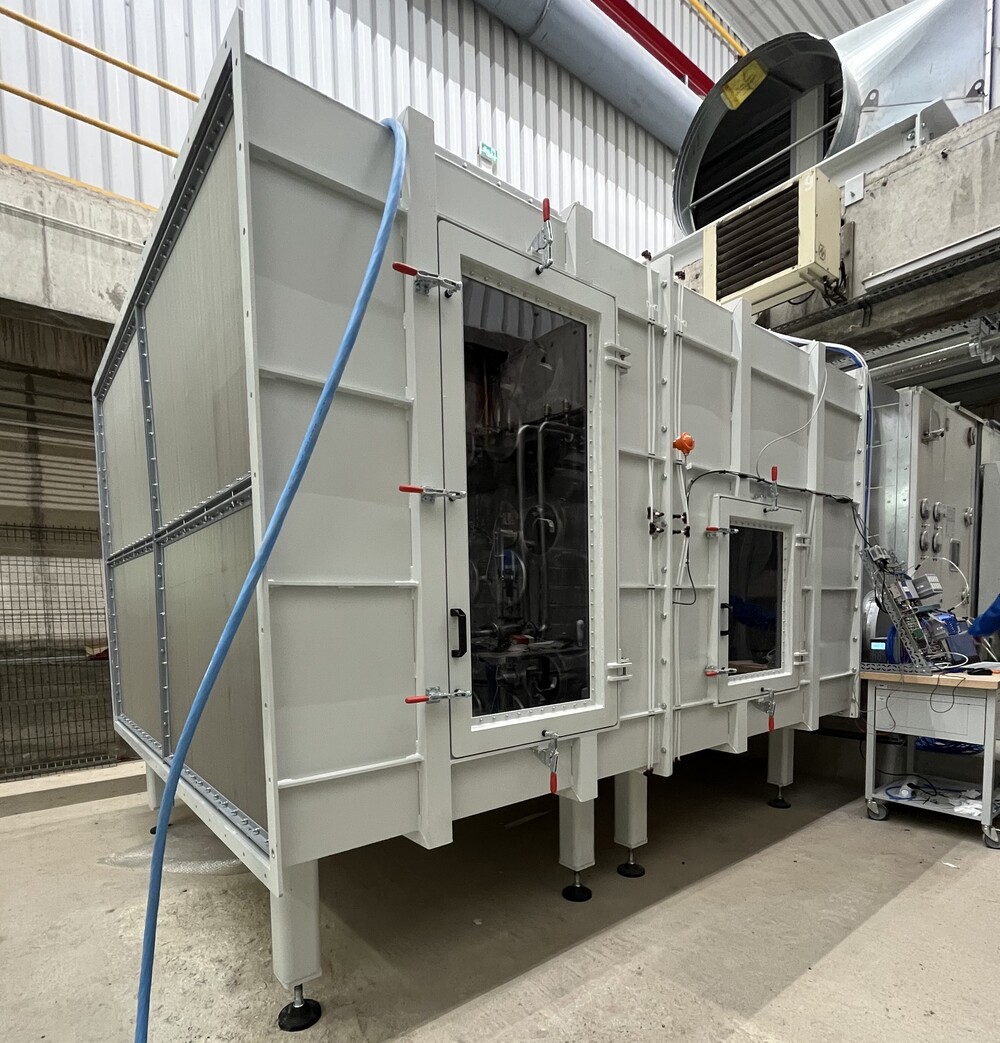
AMCA 210 Test chamber for metrological control of the blowing airflow of each test facility at fixed throughput
Location: EDF testing facility, Paris - France
Application: testing laboratory
HW VENTILATION’S ROLE
EDF selected HW Ventilation as the only supplier of an AMCA 210 chamber to be placed inside a complex testing facility. The chamber supplied by HW Ventilation has to interface an air handling unit (AHU) that provides air conditioning in order make sure that the airflow rate in the test facility provided by the AHU is fixed with low uncertainty during every test.
SCOPE OF THE SUPPLY
THE CHALLENGE
To design an AMCA 210 chamber that would fit the space constraints of the client’s laboratory, while granting the required performance levels.
The chamber had to be installed inside an already existing testing facility and needed to be constructed according to AMCA 210 standard. The AHU was already in place at the client’s laboratory and couldn’t be moved to fit the test chamber. No auxiliary fans were needed, since the chamber had to be used to keep the AHU’s airflow under control and to control that the airflow rate provided by the AHU was fixed during every test.
The chamber had to fit existing upstream and downstream connection ducts and that was another constraint of the project. The scope of HW Ventilation stopped at the hardware: EDF would interface solenoids and sensors. HW Ventilation provided the electrical specification of the equipment supplied, so that EDF could be able to interface that equipment with EDF’s input/output card.
Other requirements of the project that impacted the design of the chamber:
THE SOLUTION
AMCA 210 test chamber, without auxiliary fan, dimensions 2700 mm W x 1850 mm H x 3300 mm L.
HW Ventilation was charged with the design, construction, on-site supervision to installation and final commissioning of an AMCA 210 test chamber that fits the existing AHU’s interface and keep the ΔP at a low level (
In order to meet the project’s constraints, the nozzle wall had to be properly designed with 12 nozzles, Ø200 mm. Each of the nozzle was machined from billet high-quality aluminum alloy and finished with polishing surface treatment to pass the tolerance tests according to AMCA 210 standards. The nozzles were supplied with mechanisms for automatic opening/closing, consisting of linear and rotary air compressed actuators.
The other crucial component of the chamber were the settling means: two sequences of wire cloths positioned upstream and downstream the nozzles wall in order to provide a uniform airflow.
The instruments supplied by EDF were integrated in the chamber during the assembly at HW Ventilation.